Controlling a MaxxFan over Ethernet
I bought a MaxxFan Deluxe
model 00-05100K fan to install in my 1989 Winnebago
LeSharo. I noticed that it has an RJ45 connector — commonly known as an
ethernet connector — on the circuit board, and wondered what it
was used for, but I couldn’t find any useful info about it on the internet.
I thought it would be interesting to be able to control the fan with a microcontroller or a custom remote, so I took the fan apart and started investigating.
The process of the investigation is documented in this video:
MaxxFan Ethernet Port Wiring
The wires on the ethernet port1 are connected directly to the wires on the button panel of the fan, and can be used to duplicate the commands of the buttons by connecting two of the wires.
Using standard RJ45 pin wiring
numbers, with 1 being on the left side when the bump is down, the wiring is as
follows:
| Button | Pins |
|---|---|
| Up | 6, 8 |
| Down | 5, 8 |
| Auto | 4, 7 |
| In/Out | 5, 7 |
| On/Off | 6, 7 |
The MaxxFan Deluxe models 00-07000K and 00-07500K also include an auto-open
feature that is triggered by simultaneously triggering both the Up and Down
buttons.
The LED for the “HOLD” indicator is triggered with a positive voltage on pin 3 connected to pin 1.
There are other MaxxFan models with different button panels, such as the MaxxFan Plus model that has a Rain Sensor button on its control panel. If you are aware of any wiring differences on other models, let me know and I will update this post to reflect those.
I have added some new info on the phone jack below.
Electronics
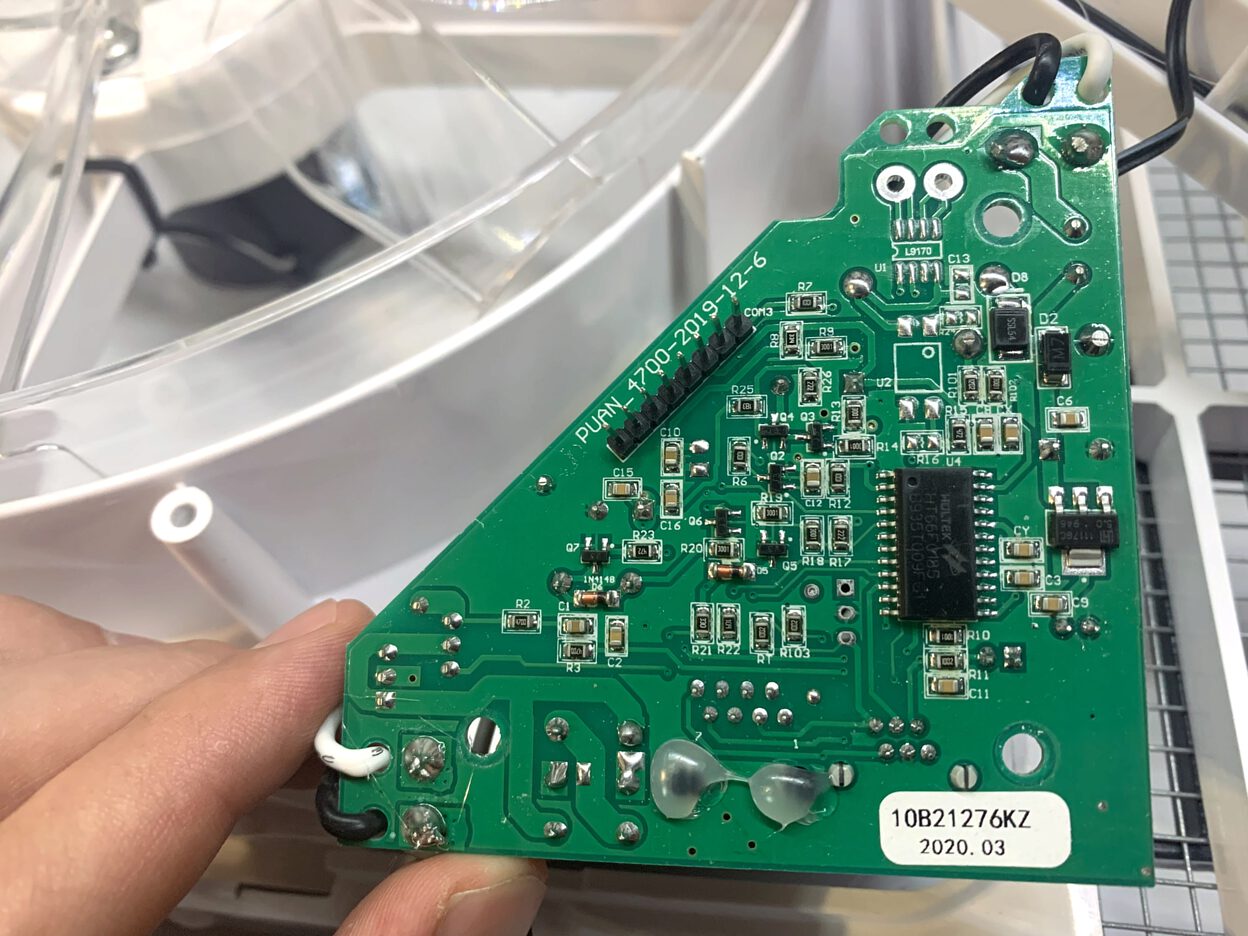
To determine the wiring of the connector, I took apart the fan and inspected the circuit board and control panel.
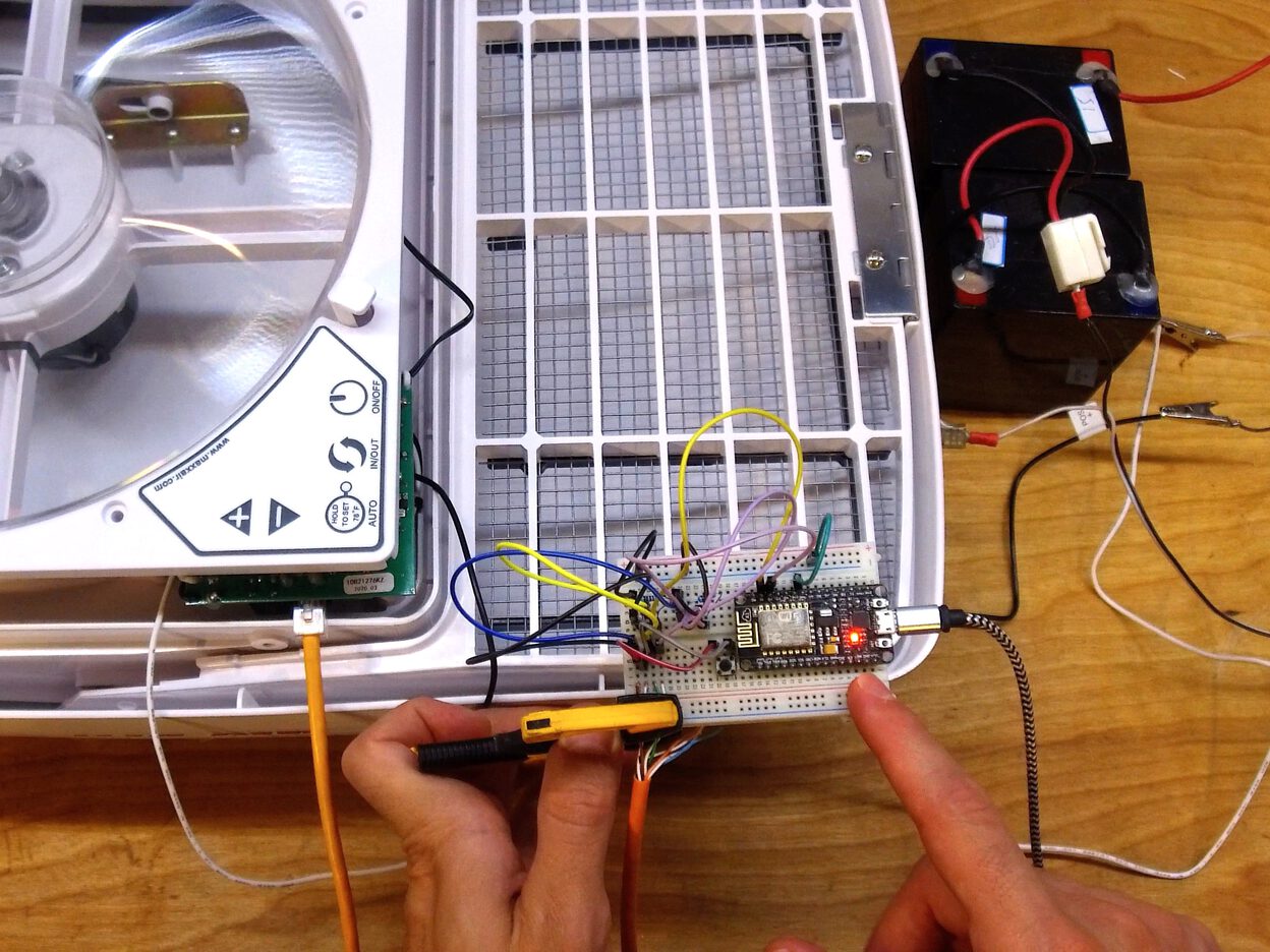
Controlling the fan with a microcontroller. 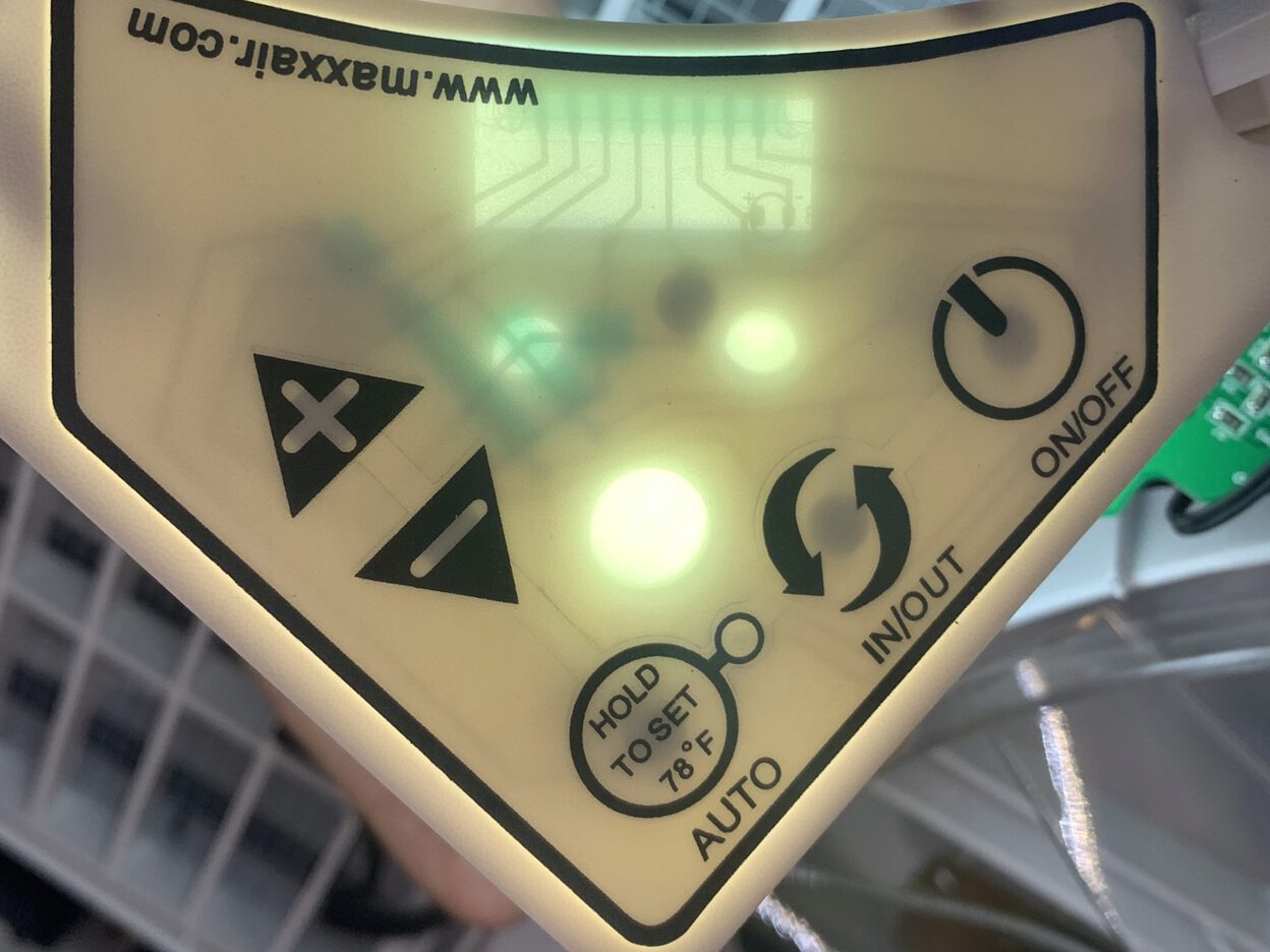
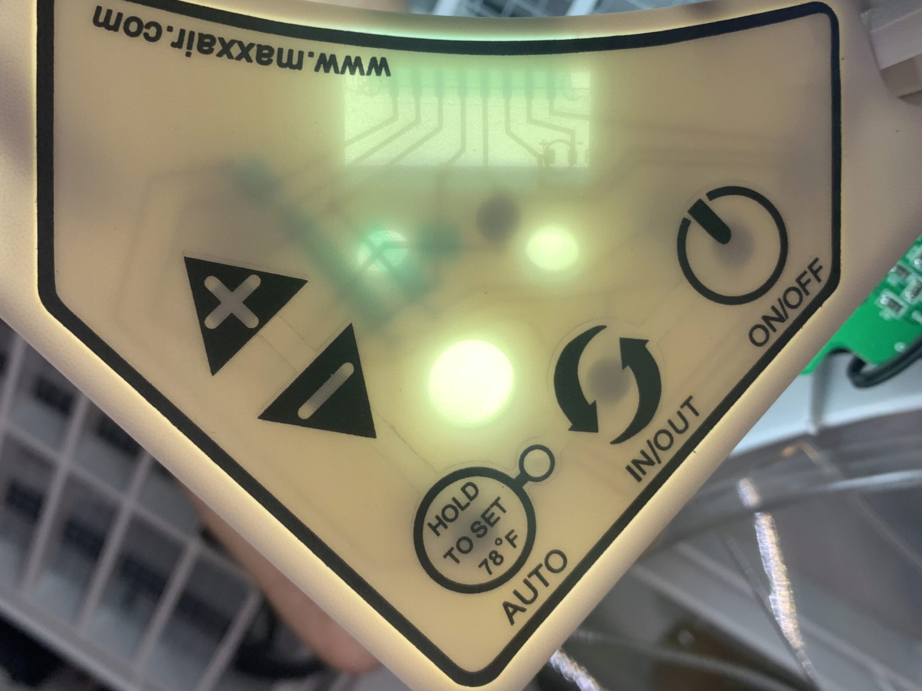
The traces in the control panel are visible when backlit. 

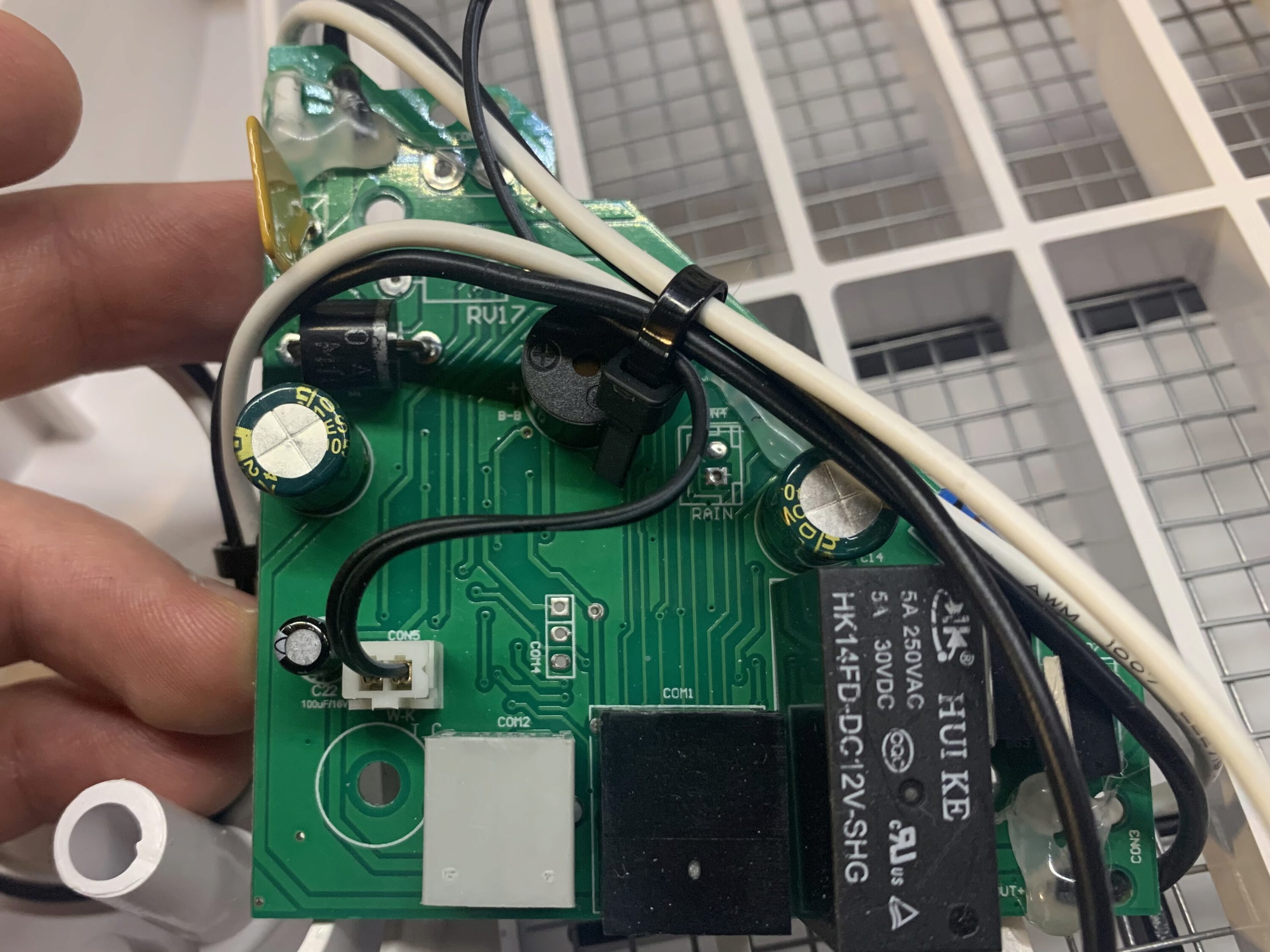

I had success using a simple NPN transistor circuit to control each button individually, the details of which can be seen below.
However, I made a large oversight when testing this out in the video, and
using plain transistors wired as described to control all the buttons will not
work because the buttons are implemented as a key matrix
with shared connections. For example, if I were to tie pin 8 to ground to
control up/down, and pin 7 to ground for the other functions, 8 and 7 would
now be connected and we could not individually control the signals.
This did not occur to me at the time, and I never made it past prototyping the simple control that I showed in the video.
A great solution to this would be to use optocouplers instead of transistors, which would keep the signals electrically isolated and is a more pure representation of simulating the button press.
In fact, someone created a great looking custom PCB that you can buy called the VanTurtle Fan Controller that does this, and can control two MaxxFan units at once. This would be pretty cool for automating intake from one and exhaust from the other.
Controlling the board requires an external microcontroller like an ESP32 or Raspberry Pi, which communicates with the device over I2C, and has a library written in Python that can be used to get up and going.
You could also probably use something like this 8-channel Optocoupler board.
The Phone Jack
Chris wrote in with some info about the phone jack, and here’s what I’ve figured out, although have not tested any of this myself.
It seems that while the ethernet jack is pretty much just an interface to the built-in button panel, the phone jack ties into the control chip on the circuit board in its own way and provides some different functionality than just pressing the buttons on the built-in control panel. MaxxAir uses the phone jack for their 4-key wired remote, which has some different functionality, like toggling between fan speeds with a single button.
What’s known as a “phone jack” is technically the RJ11, RJ14, or RJ25 connector. These represent a connection with 2, 4, or 6 wires, respectively. In this case, the MaxxFan has 6-wire connection, so it is using the RJ25 connector. A 4-wire or 6-wire connection is capable of controlling the fan as follows:
| Function | Pins |
|---|---|
| Fan On, Cycle Speeds | 2, 4 |
| Fan Off | 2, 5 |
| Vent Open | 3, 5 |
| Vent Closed | 3, 4 |
I’m not sure what’s on pins 1 and 6, though it appears from the circuit board traces that pin 6 on the RJ25 is connected to pin 3 on the RJ45. It also looks like pin 5 on the RJ25 is pin 7 on the RJ45.
Chris also had the great idea of filling the piezo buzzer with some hot glue to almost silence the beep sound.
Finally, Chris wrote a bit about detecting the fan speed and direction. The fan speed is set using a PWM signal. I believe that the “white” wire referenced in the following is pin 5 and “black” is pin 2. I will reach out for more clarification, but this is what he wrote about that:
I finally ended up figuring out that the full voltage is on one terminal and then some variation on the other terminal. at 100% it’s 0, but it increases as the speed goes down. For example, at 100% in exhaust the black wire goes from 0v to 11.52v in a few volt increments until its at roughly 0v at 100% speed. For intake, it’s the white wire that changes. In both cases, the other wire has the full voltage. That was enough for me as I was trying to hook up a shelly uni and detect fan direction. with your help I was able to control the direction and with the RJ11 I can toggle between three speeds. The uni has two outputs, two binary inputs, and an ADC input. So I can detect the voltage change on one wire and use the sensor to detect 1 or > .6V on the other so I can determine state.
Transistor Circuit
For posterity, the transistor circuit I used can be wired as follows, using a resistor to connect the signal wire to the base pin, and is detailed in the video above.
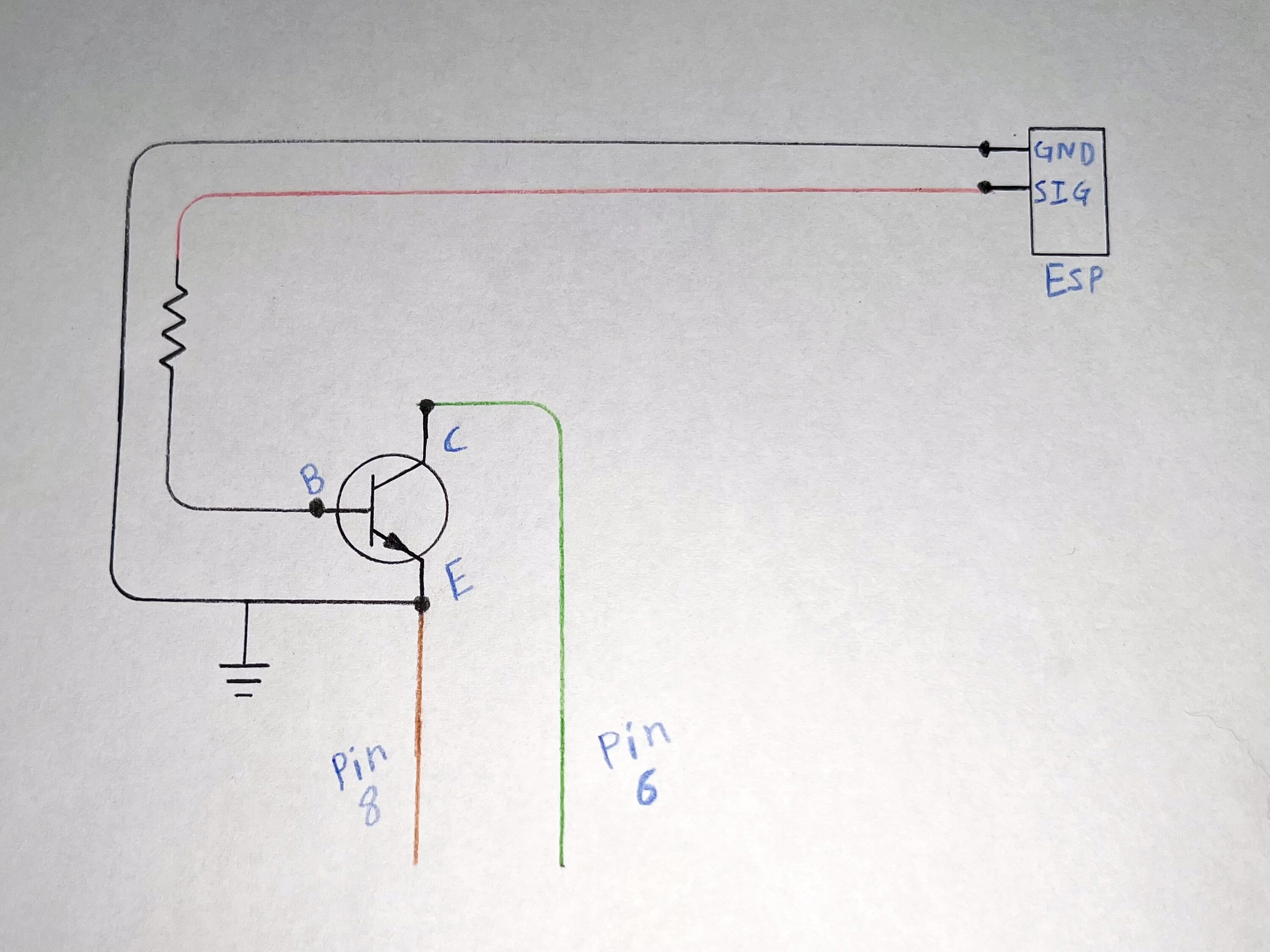
I used an 2N2222 transistor with a 1kΩ 1/4 watt resistor.
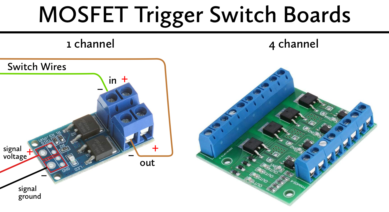
I haven’t tested this personally, but I believe another good option would be to use a MOSFET Trigger Switch Board to do this. They are affordable and include screw terminals that would make the connection to the switched device easy.
These boards are designed for higher loads and can drive lights or motors with PWM signals, but I believe they can be used as a simple switch too, as it is basically a more robust version of the schematic above. I believe you would wire one side of your switch to the negative input, and the other side to the negative output, as the ground side of the circuit is switched.
Products
-
I am using the term “ethernet” because it is known colloquially, but of course the fan does not use the ethernet protocol, but rather simply utilizes the cable and RJ45 connector because it’s a cheap and easy way to get an eight-wire connection. ↩